bridge
1www.worldbridge.org
bridge
2www.worldbridge.org
Bridge
bridge
See radio-source structure.Bridge

bascule bridge


drawbridge
footbridge


sidewalk bridge

skywalk


suspension bridge

swing bridge
What does it mean when you dream about a bridge?
Bridges often indicate literal travel. They also frequently represent life transitions. Because bodies of water symbolize the subconscious as well as the emotions, a bridge may indicate a structure that keeps one from falling into one’s subconscious or into one’s emotions (as in “bridge over troubled water”). Bridges are also links between two otherwise separated shores. Any one of these connotations might be indicated, and thus bridge images must be interpreted in the larger context of the dream.
bridge
[brij]Bridge
A structure built to provide ready passage over natural or artificial obstacles, or under another passageway. Bridges serve highways, railways, canals, aqueducts, utility pipelines, and pedestrian walkways. In many jurisdictions, bridges are defined as those structures spanning an arbitrary minimum distance, generally about 10–20 ft (3–6 m); shorter structures are classified as culverts or tunnels. In addition, natural formations eroded into bridgelike form are often called bridges. This article covers only bridges providing conventional transportation passageways.
Bridges generally are considered to be composed of three separate parts: substructure, superstructure, and deck. The substructure or foundation of a bridge consists of the piers and abutments which carry the superimposed load of the superstructure to the underlying soil or rock. The superstructure is that portion of a bridge or trestle lying above the piers and abutments. The deck or flooring is supported on the bridge superstructure; it carries and is in direct contact with the traffic for which passage is provided.
Bridges are classified in several ways. Thus, according to the use they serve, they may be termed railway, highway, canal, aqueduct, utility pipeline, or pedestrian bridges. If they are classified by the materials of which they are constructed (principally the superstructure), they are called steel, concrete, timber, stone, or aluminum bridges. Deck bridges carry the deck on the very top of the superstructure. Through bridges carry the deck within the superstructure. The type of structural action is denoted by the application of terms such as truss, arch, suspension, stringer or girder, stayed-girder, composite construction, hybrid girder, continuous, cantilever, or orthotropic (steel deck plate).
The two most general classifications are the fixed and the movable. In the former, the horizontal and vertical alignment of the bridge are permanent; in the latter, either the horizontal or vertical alignment is such that it can be readily changed to permit the passage beneath the bridge of traffic. Movable bridges are sometimes called drawbridges in an anachronistic reference to an obsolete type of movable bridge spanning the moats of castles.
A singular type of bridge is the floating or pontoon bridge, which can be a movable bridge if it is designed so that a portion of it can be moved to permit the passage of water traffic.
The term trestle is used to describe a series of short spans supported by braced towers, and the term viaduct is used to describe a high structure of short spans, often of arch construction.
Fixed bridges
This type of construction is selected when the vertical clearance provided beneath the bridge exceeds the clearance required by the traffic it spans. For very short spans, construction may be a solid slab or a number of beams; for longer spans, the choice may be girders or trusses. Still longer spans may dictate the use of arch construction, and if the spans are even longer, stayed-girder bridges are used. Suspension bridges are used for the longest spans.
Beam bridges consist of a series of beams, usually of rolled steel, supporting the roadway directly on their top flanges. The beams are placed parallel to traffic and extend from abutment to abutment. Plate-girder bridges are used for longer spans than can be practically traversed with a beam bridge. In its simplest form, the plate girder consists of two flange plates welded to a web plate, the whole having the shape of an I. Box-girder bridges have steel girders fabricated by welding four plates into a box section. A conventional floor beam and stringer can be used on box-girder bridges, but the more economical arrangement is to widen the top flange plate of the box so that it serves as the deck. When this is done, the plate is stiffened to desired rigidity by closely spaced bar stiffeners or by corrugated or honeycomb-type plates. These stiffened decks, which double as the top flange of the box girders, are termed orthotropic. The wearing surface on such bridges is usually a relatively thin layer of asphalt.
Truss bridges, consisting of members vertically arranged in a triangular pattern, can be used when the crossing is too long to be spanned economically by simple plate girders. Where there is sufficient clearance underneath the bridge, the deck bridge is more economical than the through bridge because the trusses can be placed closer together, reducing the span of the floor beams.
The continuous bridge is a structure supported at three or more points and capable of resisting bending and shearing forces at all sections throughout its length. The bending forces in the center of the span are reduced by the bending forces acting oppositely at the piers. Trusses, plate girders, and box girders can be made continuous. The advantages of a continuous bridge over a simple-span bridge (that is, one that does not extend beyond its two supports) are economy of material, convenience of erection (without need for falsework), and increased rigidity under traffic. The disadvantages are its sensitivity to relative change in the levels of supporting piers, the difficulty of constructing the bridge to make it function as it is supposed to, and the occurrence of large movements at one location due to thermal changes.
The cantilever bridge consists of two spans projecting toward each other and joined at their ends by a suspended simple span. The projecting spans are known as cantilever arms, and these, plus the suspended span, constitute the main span. The cantilever arms also extend back to shore, and the section from shore to the piers offshore is termed the anchor span. Trusses, plate girders, and box girders can be built as cantilever bridges. The chief advantages of the cantilever design are the saving in material and ease of erection of the main span. The cable-stayed bridge, a modification of the cantilever bridge which has come into modern use, resembles a suspension bridge. It consists of girders or trusses cantilevering both ways from a central tower and supported by inclined cables attached to the tower at the top or sometimes at several levels.
The suspension bridge is a structure consisting of either a roadway or a truss suspended from two cables which pass over two towers and are anchored by backstays to a firm foundation. If the roadway is attached directly to the cables by suspenders, the structure lacks rigidity, with the result that wind loads and moving live loads distort the cables and produce a wave motion on the roadway. When the roadway is supported by a truss which is hung from the cable, the structure is called a stiffened suspension bridge. The stiffening truss distributes the concentrated live loads over a considerable length of the cable.
Since the development of the prestressing method, bridges of almost every type are being constructed of concrete. Prior to the advent of prestressing, these bridges were of three types: (1) arches, which were built in either short or long spans; (2) slab bridges of quite short spans, which were simply reinforced concrete slabs extending from abutment to abutment; and (3) deck girder bridges, consisting of concrete slabs built integrally with a series of concrete girders placed parallel to traffic. The advent of prestressed concrete greatly extended the utility and economy of concrete for bridges, particularly by making the hollow box-girder type practicable. See Prestressed concrete
Movable bridges
Modern movable bridges are either bascule, vertical lift, or swing; with few exceptions, they span waterways. They are said to be closed when set for the traffic they carry, and open when set to permit traffic to pass through the waterway they cross. Bascule and swing bridges provide unlimited vertical clearance in the open position. The vertical clearance of a lift bridge is limited by its design.
The bascule bridge consists primarily of a cantilever span, which may be either a truss or a plate girder, extending across the channel. Bascule bridges rotate about a horizontal axis parallel with the waterway. The portion of the bridge on the land side of the axis, carrying a counterweight to ease the mechanical effort of moving the bridge, drops downward, while the forward part of the leaf opens up over the channel much like the action of a playground seesaw. Bascule bridges may be either single-leaf, where rotation of the entire leaf over the waterway is about one axis on one side of the waterway, or double-leaf, where the leaves over the waterway rotate about two axes on opposite sides of the waterway.
The vertical-lift bridge has a span similar to that of a fixed bridge and is lifted by steel ropes running over large sheaves at the tops of its towers to the counterweights, which fall as the lift span rises and rise as it falls. If the bridge is operated by machinery on each tower, it is known as a tower drive. If it is driven by machinery located on the lift span, it is known as a span drive.
Swing bridges revolve about a vertical axis on a pier, called the pivot pier, in the waterway. There are three general classes of swing bridges: the rim-bearing, the center-bearing, and the combined rim-bearing and center-bearing. Rim-bearing bridges are supported on circular girder drums on rollers, center-bearing on a single large bearing at the center of rotation.
Substructure
Bridge substructure consists of those elements that support the trusses, girders, stringers, floor beams, and decks of the bridge superstructure. Piers and abutments are the primary bridge substructure elements. Other types of substructure, such as skewbacks for arch bridges, pile bents for trestles, and various forms of support wall, are also commonly used for specific applications.
Degradation
Many factors can cause bridges to degrade and become structurally deficient and in need of repair. Two environmental factors that cause significant damage to primarily concrete components in bridges are excessive changes in temperature and freeze-thaw cycles in the presence of moisture. Steel structures are vulnerable to corrosion, especially in prolonged moisture environments. Use of deicing salts on concrete pavements and bridge decks produces chemical reactions that accelerate the corrosion of reinforcing steel. A significant cause of bridge damage is vehicular impact and fatigue from repeated truck loads. Special loads, such as seismic, wind, and snow, also may produce dramatic degradation of bridge structures. See Mechanical vibration
Strengthening techniques
The strengthening of concrete bridges is generally achieved by replacing the damaged material, incorporating additional structural members, as in external prestressing, or increasing the size and capacity of existing members.
Repair techniques
Numerous repair techniques have evolved for concrete members in both bridges and buildings for replacing damaged concrete, repairing cracks, and repairing corroded reinforced steel bars. Steel bridges are most often strengthened by the addition of new steel members or smaller elements. Steel welding and bolting are well-developed techniques for steel connections. Thus, strengthening of steel bridges is perhaps more defined than for the concrete bridges. Techniques for repairing steel bridge elements include flame straightening, hot mechanical straightening, cold mechanical straightening, welding, bolting, partial replacement and complete replacement.
bridge
Bridge
Al SiratBRIDGE
(1)bridge
(networking, hardware)Every network should only have one root bridge.
See also gateway, router.
bridge
(1) To cross from one circuit, channel or element over to another.(2) See Wi-Fi bridge, wireless bridge and conference bridge.
(3) A device that connects two LAN segments together. Bridges are inserted into the network to keep traffic contained within the segments to improve performance. By monitoring which station acknowledged receipt of the address, bridges learn which nodes belong to the segment and maintain their own address tables. Multiport bridges have more than two ports and perform a switching function like a LAN switch.
Bridges vs. Routers
Bridges work at the non-routable data link layer 2 and are not concerned with the network protocol (typically IP). Routers work at the routable layer 3 and inspect the network protocol. Since bridges do not have to glean routing information, they are faster than routers.
A type of bridge that connects disparate networks, such as Ethernet and Token Ring, is called a bridge router. See LAN, transparent bridge, repeater, router, gateway and hub.
 |
Bridge
(dreams)Bridge
a structure that provides a path over an obstacle. Bridges are classified according to the type of obstacle—bridges across rivers and other watercourses (bridges proper), across roads (overpasses), and across gullies and ravines (viaducts and trestles); according to the function of the path—railroad bridges, highway bridges, municipal bridges, footbridges, and bridges for integrated traffic, for the passage of water-ways (canal bridges), for water supply (aqueducts), and for gas and petroleum pipes; and according to the material of the main components—wooden, masonry, reinforced-concrete, and steel bridges.
The cost of erecting bridges accounts for up to 15 percent of the total construction cost of a road; on modern high-speed highways it is even higher. There are special requirements for the strength, safety, and durability of bridges. In addition, the design of a bridge should meet the requirements of industrial fabrication and mechanized erection, thus assuring rapid construction and high-quality workmanship.
Bridges usually consist of spans and piers. A vehicle roadway, as well as footways and pipelines, is laid on the bridge span. A distinction is made between river spans (over the navigable part of a river) and shore spans (over the remaining part). The roadway of a span may be below or above the supporting structure, as well as in the middle. The intermediate supports for a bridge are called piers, and the end supports are called abutments. The latter join the bridge to the embankments of the approaches. The loads on the span are transmitted to the piers through bearing parts. Other bridge systems are known, such as the frame type, in which the span and pier are a single unit (in such cases no bearing parts are installed).
The principal dimensions of a bridge (see Figure 1) are the total length L; the effective spans l1, l2, and l3 of the span structures, as measured between the centers of the support points; the internal widths l01, l02, and l03 of the piers; and the width of the roadway and sidewalks. The position of the structures with respect to height is described by marks (heights above an arbitrary horizon) for the roadway level R, the low-water level LW, the high-water level HW, and the base of the pier foundations F. The length of a bridge across a watercourse depends on its aperture, which is the sum of the internal widths between the piers minus the embankment cones. The aperture is found from hydraulic computations.
The height of a bridge (mark R) and the internal widths for the principal spans across navigable rivers are usually dictated by the conditions for the passage of ships. For overpasses the internal widths and the level of the roadway are dictated by the dimensions of the road beneath. In other cases, the level of the roadway is usually determined by the layout of the road passing across the bridge; the number and length of the spans are chosen on the basis of the lowest cost by comparing several versions. The width of the roadway and catwalks (overall bridge dimension), as well as the width and height of the free space under the bridge (navigation clearance), must provide for the passage of land and water transportation of the expected density. In the USSR the width of the roadbed on a bridge for a single-track railroad is 4.9

m (including the catwalks). On a highway bridge the width of the roadway is set according to the number of traffic lanes (the width of a lane is 3.5–3.75 m).
A distinction is made among girder, arch, frame, suspension, guy, and combination bridges, depending on the basic design. A special group is formed by floating bridges, drawbridges, and prefabricated bridges.
Girder bridges have spans with a supporting structure in the form of continuous beams (girders) or through trusses, which may be simple (continuous; Figure 2, a) or cantilevered, with ends (cantilevers) that extend to adjacent spans by and are connected by hinges to simple beams suspended from the spans (Figure 2,b). Continuous (through) beams are more complicated in design than simple beams, but they are more economical and provide a smoother contour for the bridge roadway, which is especially important for high-speed traffic.
Arch bridges (Figure 2,c) require smaller consumption of materials for spans than do girder bridges. On the other hand, their piers must be designed to withstand horizontal forces, and therefore the cost of their construction is usually higher. If a tie beam is used (Figure 2,d), the piers are relieved of the thrust effect, but in this case the expenditures for the span structure are increased.
The piers of frame bridges (columns or pedestals) are rigidly connected to the spans by collar beams. A collar beam may be connected to several pedestals (Figure 2,e). Also widely used are bridges consisting of separate T-shaped frames, which are interconnected by hinges (cantilever-frame bridges) or beams
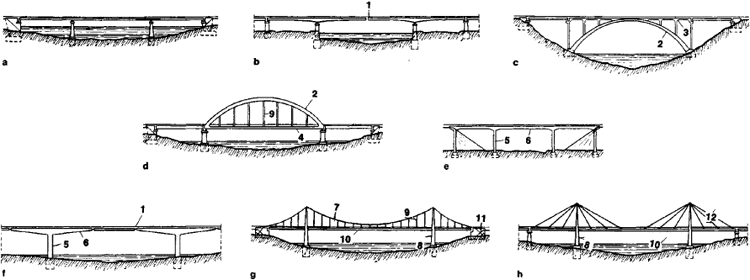
mounted on the ends of the collar beams (suspension-frame bridges, Figure 2,f).
Suspension bridges (Figure 2,g) are similar in function to arch bridges, but the load-bearing elements are under tension and are convex downward, so that the thrust acts on the piers toward the center of the span. Guy bridges (Figure 2,h) closely resemble suspension bridges in design.
The load-bearing structures of combined systems blend elements of various types of bridges (for example, girder and arch bridges).
History. The construction of major bridges began in the era of the slaveholding society. Many stone and wooden bridges and aqueducts were constructed in ancient Rome, which had developed a network of roads totaling about 75, 000 km. The stone bridges that have been partially preserved have solid, largely semicircular, arches with small spans, and piers one-third to one-half of the span in width. Light wooden bridges on piles, as well as floating bridges, were also built; the latter were frequently used for military purposes.
During the Middle Ages the development of cities and the expansion of commerce necessitated the construction of many bridges; several unique masonry bridges of that period have substantial spans, smoother arches, and narrower supports (for example, the bridge across the Adda River in Trezzo, Italy, with a span of 72.25 m).
Bridges have been known in Russia since antiquity. The Tales of Bygone Years tells of bridge-building in the mid-tenth century. A floating bridge across the Dnieper at Kiev is mentioned in the chronicle (1115). Wooden girder bridges on piers consisting of log frameworks filled with stone (cribs) were also constructed. There was extensive bridge-building (mainly masonry) in Armenia and Georgia.
In the 16th and 17th centuries, both land and water communications developed. Bridges with large spans were required for the passage of ships. In the 18th century the span of wooden bridges on masonry piers reached 119 m (the bridge across the Limmat River in Germany). An outstanding achievement of the time was a wooden arch bridge across the Neva River, with a span of 298 m, designed by the talented self-educated Russian I. P. Kulibin.
Beginning in the late 18th century, metal was used in bridge construction. The first metal (cast iron) bridge was built in Great Britain across the Severn River in 1779. It had a span of about 30 m, which was covered by cast iron arches. Cast iron arch bridges became commonplace in other countries, including Russia. Such a bridge (now the Lieutenant Shmidt Bridge) was erected in St. Petersburg in 1850 by the Russian engineer S. V. Kerbedz; it had seven spans, 45–47 m each.
Several large suspension bridges (with iron chains), with spans of up to 265 m, were erected in the first half of the 19th century. However, owing to imperfect design and inadequate rigidity, many bridges collapsed because of the action of the wind or the increased vibration amplitudes during the passage of large numbers of people marching in step (the resonance phenomenon). In the mid-19th century the erection of steel girder bridges began. One of the first was the Britannia Railroad Bridge, constructed in Great Britain by the engineer R. Stephenson. Its spans were continuous tubular beams, 70 and 140 m long. The first attempts at analysis and testing of bridges with models during design and construction were made in this period. A theory of bridge design was developed. Of great importance was the research of the Russian engineer D. I. Zhuravskii, who developed methods of calculating girder frames and beams for transverse forces and who built several major bridges on the St. Petersburg-Moscow railroad.
The steel bridge with girder spans, frequently using through trusses for medium and large spans, became the principal type in the second half of the 19th century. The Russian school of bridge-building—and, in particular, professors N. A. Beleliub-skii and L. D. Proskuriakov—performed a great service in the development of new designs and forms of spans and in the improvement of their calculations. The bridge across the Volga at Syzran’, constructed between 1875 and 1881 according to a design by Beleliubskii, was 1, 443 m long (13 spans of 111 m each) and was the largest in Europe at that time.
In the 20th century the growth of industrial production and advances in construction work brought about the further development of bridge-building; the lengths covered by steel spans increased substantially. Among the large structures erected were a cantilever girder bridge across the St. Lawrence River in Quebec, Canada (1917), with a span of 549 m, and the arch bridge across the Kill van Kull in New York (1931), with a span of 503.8 m. In 1937 a suspension bridge with a main span of 1, 280 m was built across the Golden Gate in San Francisco.
Large metal bridges have been built in the USSR across the Volga at Gorky and Saratov (1935) and across the Dnieper at Zaporozh’e (according to the plans of N. S. Streletskii). Through the efforts of E. O. Paton, the use of automatic welding for the fabrication and erection of span structures is becoming increasingly widespread.
Reinforced-concrete bridges became very common in the early 20th century. Reinforced concrete was used mainly for girder spans of up to 50 m and for larger arch spans (more than 250 m). In the 1930’s a number of unique arch bridges were erected in the USSR using cast reinforced concrete (for example, the bridge across the Moskva River at Voskresensk, the Volodarskii Bridge across the Neva River in Leningrad, and the Moskvoretskii Bridge in Moscow). The use of prefabricated reinforced-concrete units was begun in the early 1940’s. After the Great Patriotic War several long-span reinforced-concrete arch bridges were built, including one across the Dnieper with a span of 228 m. In the USSR, valuable contributions to the science and practice of bridge-building were made by G. P. Perederii, Streletskii, G. K. Evgrafov, and E. E. Gibshman; contributions abroad were made by E. Freyssinet, F. Leonhardt, R. Maillart, and R. Morandi.
Structural configurations of modern bridges. In contemporary bridge-building the principal structural members of metal bridges are made from mild and low-alloy steels; aluminum alloys are sometimes used. Solid metal beams of the same or different heights are usually used for the construction of metal railroad bridges with spans of up to 80 m and highway bridges with spans of up to 300 m. The main beams are interconnected by means of couplings. A reinforced-concrete slab for the roadway is placed over the beams. The slab is joined by special supports to the main metal beams, thus providing for their joint functioning and, as a result, reducing the quantity of metal in the structure (such bridges are called steel reinforced-concrete types; see Figure 3). Box-type main beams made of steel sheets reinforced internally by longitudinal ribs and transverse plates are also used. The slab for the roadway on such beams is made of reinforced concrete or metal. Such spans are economical, light, and rigid, which makes possible their use for large spans (up to 300 m). Metal span structures in the form of through trusses are used for the largest spans (more than 500 m). Through trusses are more economical than solid beams but are more difficult to fabricate and assemble. For the construction of a railroad track or motor-vehicle road, longitudinal and transverse beams are laid down between the trusses for the roadway, and a reinforced-concrete slab or rails are laid on the beams.

Metal arch bridges are constructed to cover spans of up to 500 m (if the foundation soils are solid). They are usually built in mountainous areas. One of the largest arch bridges crosses the Vltava River in Czechoslovakia (1967) and has a span of about 320 m.
Suspension bridges are built to cover spans exceeding 1, 000 m (for example, when crossing the mouths of deep rivers, bays, and straits, where the construction of a great number of piers is complicated and uneconomical). The cables of such bridges are made of high-strength steel wires arranged in parallel or twisted into a rope. The towers of a suspension bridge are usually box-type and made of metal; they are sometimes made from reinforced concrete. The Verrazano-Narrows Bridge (USA, 1964) has the longest span (1, 298 m).
Guy bridges are becoming more common for spans of 150–350 m. The guys that support the stiffening girder may converge at the peak of the tower or run parallel to one another. Asymmetrical single-tower arrangements are in use (a bridge across the Rhine River at Cologne, 1959). The stiffening I-beams or box beams of suspension and guy bridges are kept level by hangers or guys. For large spans (more than 500 m), the main beams are replaced by through trusses.
Reinforced-concrete bridges are divided into cast and prefabricated types. Cast bridges are poured at the construction site; prefabricated bridges are assembled from separate components that are made in special plants for reinforced-concrete structural members or at on-site areas. Reinforced-concrete girder bridges usually have a slab for the roadway and sidewalks, as well as crossbeams (plates) and main beams. The roadway slab forms part of the main beams. In the USSR extensive use is made of spans prefabricated from separate beams that cover the entire span and are interconnected by poured seams in the roadway and plate slabs and by welded metal insertion elements. If the beam reinforcement is prestressed, the beams can be divided lengthwise into individual blocks, which are delivered to the construction site from the plants. The tensioned reinforcement squeezes the blocks together, forming a beam.
Solid reinforced-concrete cantilever and frame bridges with spans of 50–200 m have become widespread. The main beams of such bridges are usually box-type beams. The most efficient means of cantilever-type construction of bridges are the frame-suspension and cantilever-frame systems, because tension for the collar beams of T-shaped frames, both during assembly and in use, arises at the upper edge, and reinforcement is needed only at the top. For continuous beams, bottom reinforcement is also necessary, which greatly complicates the work. On the other hand, there are no discontinuities in the contour of continuous beams; therefore, there has been a notable tendency toward more extensive use of continuous beams in modern bridges. In bridge-building practice there are examples of reinforced-concrete bridges with spans in the form of through trusses. However, the complexity of connecting the reinforced-concrete elements at the truss joints restricts their use.
Reinforced-concrete arch bridges with solid or free-standing arches are used for spans from 50–60 m to 200–300 m. In the USSR arch bridges are usually made from prefabricated reinforced concrete. Arch-cantilever bridges in which two half-arches are joined at the top by tie beams to form a T-shaped frame are also built. A number of large bridges have been built using this system (for example, the subway bridge in Kiev).
As motor-vehicle transportation develops, complicated, multitiered bridge-type structures are being built on highways, particularly in the cities; they curve both vertically and horizontally and consist of reinforced-concrete or steel trestles and overpasses. The curvilinear spans frequently have a box-shaped cross section.
The piers of modern metal and reinforced-concrete bridges are usually made of light cast concrete or prefabricated reinforced concrete on a natural or pile foundation.
Construction. The installation of piers is the most time-consuming, labor-intensive, and costly process in the construction of a bridge (up to 50 percent of the total cost). The hydrogeological conditions determine whether the piers are constructed in open excavations or by driving piles, massive cofferdams, caissons, and prefabricated reinforced-concrete casings. For the piers of small and medium bridges in modern construction, extensive use is made of reinforced-concrete piles, which are driven into the ground by steam, diesel, or electric vibratory pile drivers; for the construction of large bridges, tubular prefabricated reinforced-concrete shells up to 3 m in diameter are sunk by vibration pile driving or drilling.
Spans are usually erected by methods that avoid the construction of continuous falsework in river beds. Small and medium spans or large portions of them are hoisted into position on the piers by erecting cranes with a lifting capacity of up to 130 tons. For larger spans, the span is assembled on shore and then transported or floated on pontoons and placed on the piers. The most common method of bridge erection is the cantilever type, in which the structure is built out from the piers across the span. Metal spans are assembled by a crane that moves along the finished portion; the bridge elements move under the crane along a track on the assembled span. For reinforced-concrete spans, the cantilever-type method of assembly (developed in the USSR) includes the fabrication of the individual structural elements (units) at a plant and their delivery to the assembly site (usually by water) and placement in the desired location by special cranes. The joints between blocks are filled with cement mortar; adhesive joints between blocks are also used. Blocks are frequently joined by locking beams that are installed with the same cranes. Outside the USSR, the cantilever-type concreting method is used in addition to cantilever-type assembly: a sliding casing is suspended from the completed portion of a structure, the span portion is concreted, and the reinforcement is tensioned after the concrete has set. The erection of suspension bridges begins with the towers, and then temporary cables are hung and used to lay up the main cables. The final step is installation of the hangers and a stiffening beam.
Construction in the USSR is carried out by specialized organizations (bridge-building teams, trains, and mobile task forces), which are provided with equipment, mechanisms, cranes with a large lifting capacity, and stock auxiliary structural members. Bridges are usually constructed by industrial methods; only prefabricated structures are assembled at the site. All new bridges undergo tests (for temporary, moving loads), which are conducted by specialized bridge-testing stations.
Calculations. Calculations for bridges are performed mainly by the method of limiting states. Each portion of a bridge (the spans and the supports) must satisfy requirements for strength, deflection, and crack resistance under the most unfavorable combination of loads on the structure. Two kinds of loads act on a bridge: constant loads (the weight of the bridge itself and the preliminary stress on the reinforcement) and temporary loads (the weight of railroad trains or columns of motor vehicles and crowds of people on the sidewalks, tracked or wheeled live loads, wind and ice pressure, collisions of ships with the piers, impacts of traffic on the rails or sidewalks, and the forces produced by sudden braking). In seismic areas, an allowance is made for the inertia loads that arise during earthquakes. All load calculations are standardized with regard to the existing traffic load and the prospects for its increase. Methods of bridge design are based on achievements in mathematics, structural mechanics, the theory of strength of materials, and other sciences. Electronic computers are used extensively for calculations.
Trends in the development of bridge-building. The modern trend in bridge-building is characterized by increased use of prefabricated components and factory-made parts, the introduction of industrial production and operating methods, and the mechanization of the basic technological processes, along with the further development of structural systems for bridges and an increase in their maximum span.
The use of high-strength steels and light alloys and the use of welding instead of riveting is increasing in bridge construction; the structural shape of spans is being improved through the use of rigid box-type sheet components. In reinforced-concrete bridge-building the use of thin-wall components made of high-strength concrete is acquiring increasing importance, as are the standardization of the prefabricated elements for spans and piers, the creation of new types of prestressed components, and the development of standard casings and erecting units.
REFERENCES
Nadezhin, B. M. Mosty i puteprovody v gorodakh. Moscow, 1964.Gibshman, E. E. Proektirovanie dereviannykh mostov. Moscow, 1965.
Gibshman, E. E. Proektirovanie metallicheskikh mostov. Moscow, 1969.
Evgrafov, G. K. , and N. N. Bogdanov. Proektirovanie mostov. Moscow, 1966.
Stroitel’stvo mostov. Moscow, 1966.
II’iasevich, S. A. Metallicheskie korobchatye mosty. Moscow, 1970.
Nazarenko, B. P. Zhelezobetonnye mosty, 2nd ed. Moscow, 1970.
A union of architecture and engineering skill was achieved in the bridges of ancient Rome. The expressive architectonics of the massive, multiple-arch construction, almost devoid of decoration, imparts to the bridge a sense of stark power, which is characteristic of the utilitarian edifices of ancient Rome (the Alcántara bridge across the ravine of the Tagus River in Spain, A.D. 98–106, builder Gaius Julius Lacer). In metal bridge components, maximum use is made of the mechanical and physical properties of the material (metal withstands tensile forces well). Because of this quality, metal bridges became less massive than masonry bridges and acquired a more delicate outline, which is an important artistic feature (the bridge across the Douro River at Porto, Portugal, 1881–85, engineer A. G. Eiffel). Metal bridges with efficient engineering and architectural treatments have affected the architectural styles of the 20th century.
Reinforced-concrete bridges are sculpturally expressive. The dynamism and visual lightness of form often impart a singular elegance to large structures (the bridge across the Arve River in Switzerland, 1936; engineer R. Maillart). The substantial dimensions, large shapes, and distinctive outline of bridges influence the architectural aspect of a city (for example, bridges in Leningrad, Prague, and Budapest). Therefore, the structural and architectural-spatial treatment of a municipal bridge must take into account the specific conditions of its location and the natural and architectural environment.
A particularly important and complicated urban-planning problem is the search for a harmonious combination of the outline, scale, and structural design of a bridge with the long-established buildings of old cities that are often valuable from a historical and artistic standpoint. An example of a successful solution is the Alexander Nevsky bridge across the Neva River in Leningrad (1965, engineers A. S. Evdonin and others, architects Iu. I. Sinitsa and others). By repeating the outline of the other Neva bridges over the water, it is made commensurate with the scale of the river and the buildings on its esplanades.
E. K. IVANOVA
Bridge
an electrical device used to measure resistance, capacitance, inductance, and other electrical quantities. It consists of a bridge circuit, whose operation is based on comparison of the quantity being measured with a standard value of the quantity. The comparison method yields very accurate results; therefore, bridges are widely used in laboratories and industrial practice.
The simplest type of DC bridge, used in measuring effective (ohmic) resistance, is shown in Figure 1. The supply voltage (current) is connected to the input terminals A and B (on the supply diagonal). A null indicator or measuring instrument is connected to the output terminals C and D (on the measuring diagonal). By adjusting one or more variable resistors, the potentials at the points C and D can be made equal. Equilibrium is achieved when the null indicator shows no current flowing through the measuring diagonal (that is, the bridge is balanced).
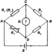
For the balanced condition of a bridge, the ratio of the resistances of the arms is given by the equation R1·R4 = R2·R3 (the equilibrium condition). To measure a resistance Rx, it is connected in one arm of the bridge—for example, as the resistance R1, If the bridge is balanced, Rx = (R2 · R3)/R4. In this method the accuracy of measurement of Rx is determined by the precision of the calibrated resistances R2, R3, and R4 and by the sensitivity of the null indicator.
The Wheatstone (four-arm) bridge shown in Figure 1 is commonly used for measuring resistances R≧1 ohm (Ω). The results of measurement of resistances R < 1 Ω with a Wheat-stone bridge are significantly affected by the resistances of the connecting leads and by contact resistances, since they are becoming commensurate with Rx. To measure resistances from 1 microhm (μΩ) to 1 Ω, double or multiarm bridges are used. Combined single and double bridges exist that are capable of measuring resistances from 1 μ to 1 Ω with an error of the order of ± 0.002 percent. Sometimes the resistances are not varied, and the results of measurement are recorded by an instrument calibrated in units of the quantity being measured and connected to the measuring diagonal; this is called the unbalanced-bridge method.
Balanced AC bridges are used to measure capacitance, inductance, coefficient of mutual inductance, and so on. The results of measurement of such quantities depend on the frequency of the voltage supplied to the bridge; therefore, measurements are usually made at some specified constant frequency. The basic circuit of an AC bridge is similar to the one shown in Figure 1, with the difference that each arm may contain an inductance coil, a capacitor, and a resistor. An AC bridge is usually balanced by adjusting two components rather than one, since the balancing of such a bridge depends on the ratio of the impedances of its arms, which in the presence of capacitances and inductances are complex quantities. The magnitudes of the quantities being measured are determined from the conditions of balancing of the bridge.
Measuring generators operating at audio frequency are the most common source of alternating current for AC bridges. Industrial alternating current (50 hertz) is used less frequently. A moving-coil galvanometer is used as the null indicator for a DC bridge; vibration galvanometers, telephones, electronic pointer indicators, or electron-beam instruments are used for AC bridges. In modern bridges the balancing process is automated, and the results of a measurement are displayed as a number on a readout device. Such instruments are called digital bridges.
REFERENCES
Gorodovskii, A. F. Mosty postoiannogo toka. Moscow-Leningrad, 1964.Nizhnii, S. M. Mosty peremennogo toka. Moscow-Leningrad, 1966.
Shkurin, G. P. Spravochnik po elektro- i elektronno-izmeritel’nym priboram. Moscow, 1972.
G. P. SHKURIN
Bridge
of a ship. (1) Navigational, or captain’s, bridge, an elevated superstructure on the upper deck of a ship that provides an all-around view; it houses the equipment and instruments required to run the ship, as well as facilities for visual or acoustic signals.
(2) Fore-and-aft bridge (gangway), constructed to run lengthwise above the upper deck of a ship (usually a tanker) to connect the ship’s superstructures. It permits the crew to move about safely during a storm.