modulator
[′mäj·ə‚lād·ər]Modulator
Any device or circuit by means of which a desired signal is impressed upon a higher-frequency periodic wave known as a carrier. The process is called modulation. The modulator may vary the amplitude, frequency, or phase of the carrier.
There are many ways to accomplish amplitude modulation, but in all cases a nonlinear element or device must be employed. The modulating signal controls the characteristics of the nonlinear device and thereby controls the amplitude of the carrier. See Amplitude-modulation detector, Amplitude modulator
The frequency modulator usually changes the effective capacitance or inductance in the frequency-determining LC circuit of the oscillator. However, other techniques can be used. For example, a multivibrator can be used to generate carrier frequencies up to a few megahertz, and the multivibrator frequency can be modulated by controlling the base, gate, or grid bias supply voltage. See Frequency modulator
modulator
modulation
Modulation refers to altering an oscillating, fixed-frequency carrier wave (radio wave) in order to transmit data, audio or video from one location to another, either wired or wireless. The data are merged into the carrier.At the receiving end, a tuner latches onto the particular carrier frequency and a demodulator circuit isolates the data from the carrier. See carrier.
In traditional analog telephony, modulation alters a DC current. In such a conversation, both parties are modulating the current simultaneously.
Amplitude, Frequency and Phase
There are three basic types of modulation: amplitude modulation (AM) varies the voltage; frequency modulation (FM) varies the frequency, and phase modulation (PM) varies the angle of the wave. In quadrature amplitude modulation (QAM), both amplitude and phase are modified. See amplitude modulation, frequency modulation, phase modulation and QAM.
 |
| Analog Radio |
|---|
| In AM/FM radio, the radio station's carrier frequency has been modulated by the analog sound waves. |
Modulator
(in electronics and telecommunications), a device that produces modulation (control of the parameters of a high-frequency electromagnetic information carrier in accordance with electrical signals of the transmitted message). A modulator is mainly a component of transmitting apparatus for electrical communication and radio broadcasting. The information carrier is usually harmonic oscillations or waves at a frequency of about 104−1015 hertz (which is called the carrier or subcarrier frequency).
A distinction is made among amplitude, frequency, phase, and complex modulation (for example, in single-sideband transmission), depending on the parameter of the harmonic oscillations or waves that is varied; the type of modulator is classified accordingly. In pulse-code modulation the information carrier is a regular sequence of electrical pulses whose parameters (amplitude, width, frequency, or phase of the repetitions) are controlled by corresponding types of pulse modulators. The modulating electrical signals of the message being transmitted may have very different forms: from simple, slow telegraph dispatches in the form of dots and dashes or oscillations in the audio-frequency range for the transmission of speech and music to the complicated, rapidly varying signals that are used in television or multichannel wire and radio-relay communications. Amplification of the modulating oscillations is often included in the function of the modulator.
A necessary requirement for modulation is that the modulating oscillation must vary with time much more slowly than the modulated oscillation. Consequently, in any modulator the interacting circuits of the modulated oscillations or waves are combined with circuits for the lower-frequency modulating signal. The determining element in a modulator is the control element, which permits a signal to act on the parameters of the modulated oscillations or waves. As of 1974 the electron tube as a universal control element had been retained mainly as a modulator in high-power radio transmitting apparatus (“modulator tubes” were especially developed for this purpose). For transmitter powers of up to 0.5 kilowatt, tubes have been successfully superseded by transistors and other semiconductor devices. In addition to semiconductor devices, klystrons and traveling-wave tubes are also used in apparatus operating at superhigh frequencies. (For information on modulators for the optical wavelength range, see.)
In amplitude modulation, the modulator varies the amplitude
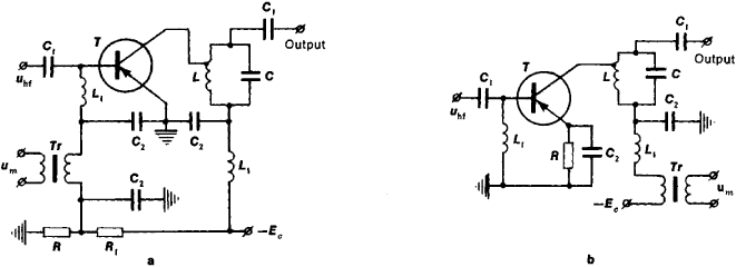
of the carrier-frequency oscillations that are being generated or amplified. In a grid modulator for an electron-tube radio transmitter the modulating voltage acts on the input (grid) circuit of a high-frequency oscillator or amplifier, whereas in a plate modulator it acts on the output (plate) circuit of the oscillator or amplifier tube. A grid modulator is more economical, but a plate modulator can provide a higher degree of modulation with less distortion. In transistorized radio transmitters the base and collector modulators (Figure 1, a and b) are the transistor analogues of the grid and plate tube modulators, respectively. To obtain amplitude-modulated oscillations with suppressed carrier-frequency oscillations, a balanced modulator is used.
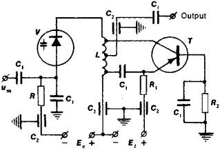
In frequency and phase modulation the control elements used in the modulators are reactive devices, in which the effective capacitance or inductance (or both) is varied by the action of the modulating signal. The reactive device is connected directly to the resonance circuit of the driving oscillator or to subsequent phase-shifting circuits of the radio transmitter. In tube modulators such a device is called a reactance tube; in transistor modulators it is called a reactance transistor. In addition, the phenomenon of phase shift in the generated oscillations, which under certain operating conditions depends on the value of the DC collector current, is used in some transistorized phase and frequency modulators. Extensive use is made of varicaps as the reactive control element in modulators (Figure 2).
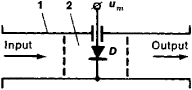
In pulse modulation the modulator control element may also be an electron tube or a semiconductor device such as a varicap (Figure 3), which cuts off or opens a microwave channel in accordance with the sign of the modulating pulse trains.
A modulator is sometimes part of amplifiers operating in various frequency ranges, from audio frequencies to superhigh frequencies. A magnetic amplifier has a modulator in the form of a DC saturable reactor, whose inductance is controlled by the current of the amplified signal. In this case it is alternating current of commercial frequency, which is higher than the spectrum of the signals (usually the commands of automatic systems), that is usually being modulated. In a dielectric amplifier the modulator is a nonlinear capacitor that controls the signal voltage by means of its capacitance. A modulator is also a component of some parametric amplifiers.
REFERENCES
Kukk, K. I., and V. G. Sokolinskii. Peredaiushchie ustroistva mnogokanall’nykh radioreleinykh sistem sviazi. Moscow, 1968.Model’, Z. I. Radioperedaiushchie ustroistva. Moscow, 1971.
Radioperedaiushchie ustroistva. Edited by B. P. Terent’ev. Moscow, 1972.
Radioperedaiushchie ustroistva na poluprovodnikovykh priborakh. Edited by R. A. Valitov and I. A. Popov. Moscow, 1973.
M. D. KARASEV